
DESIGN OF POST TENSIONED CONCRETE PORTAL PIERS
- USAMA KHAN

- Nov 2, 2021
- 5 min read
Updated: Aug 9, 2022

Portal beams are usually put to use when the placement of a single pier is not feasible. This might be due to some obstruction or otherwise when the viaduct has to cross a road and the placement of a single pier would obstruct the road.
These structures are either in RCC, steel, composite or designed with post tensioned beams.
STRUCTURE
The case we are expounding is that of a single piercap and single viaduct portal pier, which hosts tow box girder spans on either sides.
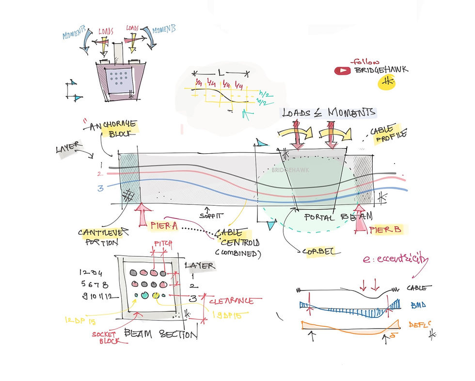
Portal piers are divided into mainly two components, the pier and the beam. The next most prominent component is the piercap. Portal beams host the piercap at the relevant location of the track centre line. The pier cap is mostly similar to the one used in the piers except that it is not supported on the pier directly. Positioning of this pier cap is tried best to arrange centrally aligned to either of the piers. Thence, depending upon the type of girder and number of the bearings required, the pedestals and the arrestors will be arranged.

PIERS
Since both the piers are separated, the geological and the geographical conditions of the two locations might have a great possibility to differ. Both the piers pier A and Pier B might have different heights, sections, governing loads, reinforcement, etc. The occurrence of pipes, rocks, etc. at one pier location might lead to proposing different pier types for either of the piers. So more often than not, we may encounter portals with piers that have unequal heights and open foundation for one and pile for another. The different types of portal piers encountered will be covered in a dedicated article in detail. Generally, a pier section has to be rectangular in shape with dimension in the range of 1 meter to 2 meter in both ways. Section width depends primarily on the direction of the governing moment with Longitudinally or transversely, using a higher width on the greater moment direction.

PIERCAP
The piercap, as indicated in the illustration, is placed exactly above the pier matching the CG with the CG of the box girder. This helps in transferring the forces effectively through the bearing to the pier and to the foundation. When taken a section of these piercap, they are trapezoidal in shape with 4 bearing pedestals placed as any normal piercap as shown in the figure. Their design is akin to the normal piercap except for t
difference in a few load cases.
PORTAL BEAMS
The beam, rectangular in section, is mostly post tensioned. A staging arrangement is required for casting in situ. Such staging arrangement have to be designed and the drawings have to be taken approval of before erection. If the beam is precast, the beam placement schedule and sequence has to be simulated on software with appropriate load stages. Post tensioning cables go through the beam as indicated. The main challenge in designing the cables is the profile and the stages of tensioning. The cable configuration is based on the governing moment case and the point of the maximum moment plane. The tensioning stages have to ensure that there is no development of negative moment. The beam length of the beam is the span of the beam.
LOADS
Loads on the portals are varied. Primary loads on the portal structures are dead loads, SIDL, live loads and launcher loads during construction.
The governing case is a subject to number of tracks, anticipated live load cases, etc. The passage of the launcher might qualify to be the governing case in case of box girder spans. And for this governing load the pier and the pier caps are designed. Loads from the launcher depend on the categorical type of launcher in question. Since the launcher places the girder on either sides, there are 3 main launcher stages that exert the maximum loads upon the piers.
MOMENTS

Design moments for the portal beam are the vertical loads on the piercap which causes eccentric sagging. Torsion on the beam section is due to the lever arm from the bearing centre to the centre line of the beam. The bearing centre is, as discussed earlier, hosted upon the flared piercap. Design moment for the pier emanates from the lateral loads with the lever arm as per the height of the pier H1 and H2. The lever arm is computed from the top of the rail to the pier bottom.
BEHAVIOUR
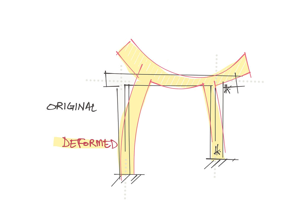
There are two main behaviors of the frame that need to be ascertained in detail. One being the deflected shape under loads and the other under the influence of post tensioning loads only as shown in the illustration.
Beam behavior under loads only generates uplift in the piers wile only tensioning force develops tension. The BMD and deflection diagram under vertical loads is indicated in the illustration. Evident from the deflection diagram is the cantilever behavior of the overhang portion of the portal beam.
MODELLING IN SOFTWARE

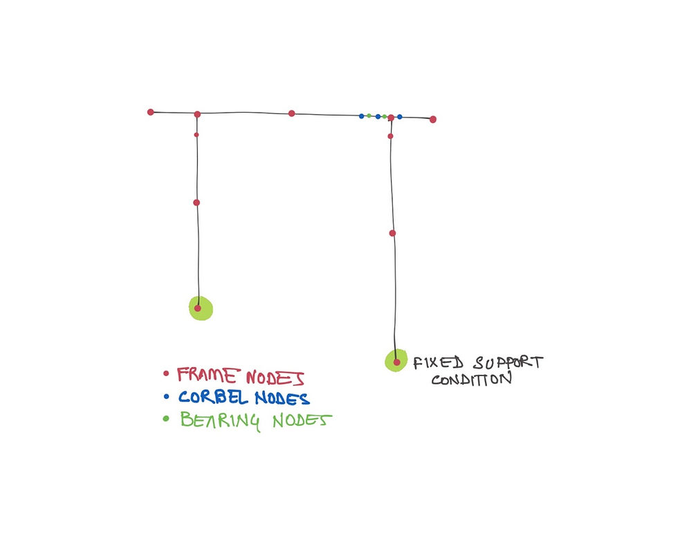
The model for such portals is usually a line model frame as indicated in sketch. I had used MIDAS Civil to model my portals. The important factors to consider are the attributes, load points, critical moment or shear points, and points at which the possibility of governing moment is anticipated. On all these points, a node has to be assigned. Ensure that the nodes divide the member into 2. If this is neglected, values might not be accurate. Watch this video which covers the node placement for a portal frame. Section properties can be better imported directly from CAD using the import section property command, otherwise, manual input of all properties can be achieved by putting in some extra time.
The beam section at the point of the piercap has to be input just the same way.
You will notice that even when the portal is a 3Dimensioanal structure, and that the point loads on the bearings are at a longitudinal offset-we will still model it in 2D only. The loads must accommodate the respective lever arm and account for the governing load cases only.
The pier is fixed at the bottom on both sides.
This video will further delve on the topic of modelling:
POST TENSIONING
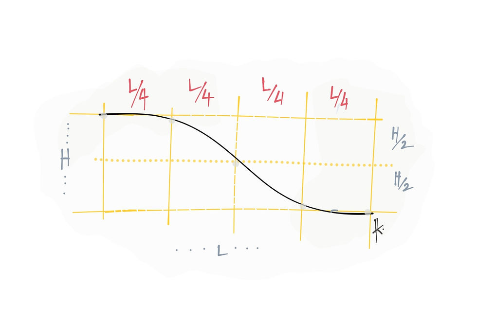
The profile of the cables, as illustrated, is designed to dip at the section of the bearings or piercap.
The value of bending moment at this juncture has to be catered to by the increased eccentricity of the cables. The subsequent moment capacity of the section is highly increased in this zone. Also, the care must be taken to not let a negative bending moment arise in the section.
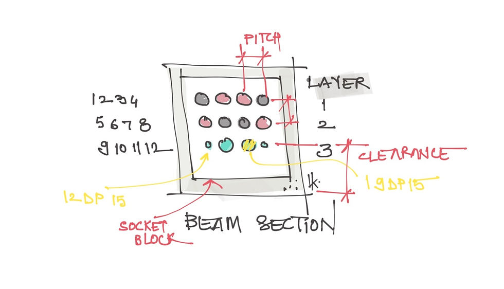
The cable profile design follows an s curve. This curve is modified as per the behaviour and the post tensioning stages. As indicated in the illustration, the cables are placed in 3 layers with 4 numbers in each layer. The cables, numbered from 1 to 12, are activated based on the construction stages. Number of strands in each cable are indicated as ‘12K15’ or ‘12DP15’ indicating 12 strands to be stressed in a cable block of 15 strands; hence 3 strands will remain un-stranded and unstressed. The cable block that hosts all the cables has to maintain enough clearance from the bottom most cables to ensure proper distribution and prevent busting of the beam.
REINFORCEMENT

The reinforcement arrangement has been sketched for better understanding. There usually are number of closed stirrups closing all the longitudinal bars. The web is mostly designed as a usual bending member and the flanges are designed as corbels. Hence the reinforcement of these corbels will follow the design requirement fully with a side reinforcement throughout the length of the beam.
Find out more about portal piers in this video
Subscribe to the BridgeHAWK® channel on #youtube
Follow us on Linkedin and stay updated!
HASHTAG
#bridges #bridgeengineering #civil #civil3d #civilengineeringworld #civilengineering #civilengineer #civilengineers #civilengineeringstudents #civilconstruction #civilengineeringdesign #civilengineeringdiscoveries #civilworks #civilengineeringlife #creativity #creativityskills #creativityisnow #bridges #bridgeengineering #bridgeconstruction #bridgedesign #bridgeinspection #bridge #bridgebuilding #structural


Comments