
GRILLAGE ANALYSIS FOR STEEL I-SECTION GIRDER BRIDGE VIADUCT
- USAMA KHAN

- Jun 29, 2021
- 6 min read
Updated: Aug 9, 2022
Grid analysis is the fundamental aspect of bridge engineering as far as understanding any bridge span is concerned
Grid analysis or grillage analysis of a span is the virtual modelling and simulation of all forms of conditions and forces upon the bridge span that can occur in its service life. The bending , shear, torsional stresses so developed within the model help us in the preliminary design of bridge girders, diaphragms, cross bracings, and decide other geometrical and structural aspects which I will further expound.
As innumerable possibilities of a span arrangement can be envisioned, I will select a case which might cover some complexities for the sake of understanding.
PROCEDURE

The span under consideration is trapezoidal in plan as illustrated. This is done so as to incorporate the curved track within a common span with the straights-in the process preventing a separate span for the curve track. Span has 8 steel girders in total of which 2 are placed at an angle. The girders are joined in the mid by 4 bracings at equal intervals and at the end their diaphragm connects them end to end. The girders are placed upon bearings of which one bearing is kept fixed. The steel plates used to fuse together the girder sections are usually in 12meter long pieces, so achieving a 30 m span continuous girder is an option farfetched. Hence the girders needs be spliced which I have indicated in the “Plan” sketch. The designer must ensure that the splice point is not encountered at the midpoint or at points where bending moment spikes. The bracing number and spacing is purely a designer’s preference as per the understanding of the girder behaviour.
The overhang portion after the diaphragms is a continuation of the girder usually 0.5m TO 0.7m in length. This is done to allow for expansion joints, arrestors, pedestals spaces, etc. a cantilevered overhang is encountered at the sides of the girders 1 and 8, on this overhang rests the crash parapet and the offset required for the minimum clearance provisions as per the relevant codes.
Now, the span hosts 3 tracks which are straight –T1, T2, T3 and 2 curved tracks –T4 & T5 as indicated. Tracks 4 merges into T2 and T% curves out of T3 respectively. We need to ensure as best possible that the tracks must align to the girders-matching the centroid of the tracks with the centroid of the girders. It is best to avoid the tracks resting on independent slabs.
SECTION

Now, in order to incorporate every aspect of the span into the analysis model, we need to dissect the span into individual components and find out their load equivalent to apply on the Grillage model.
If you refer the “Span Section” sketch you will notice that the girders are 4 in number, I have used that for the sake of simplicity. The girder placed upon the bearings must hold the slab above by the aid of the top flange and the sheeting. These slab harbours the track plinths upon a transversely sloped PCC layering and the tracks are fixed atop the plinths. The crash parapets on either sides may vary in shape and material, the loads and subsequent moments of which must be taken into consideration as will be discussed further. Trays on the parapet are for the conduits to pass along length. The cross slope is maintained to cannel off water to the drain pipe. This extra concrete is applied as an additional load on the span. The Diaphragm is itself an I-section in its section and reduces in height at the centre to allocate space for the arrestor.
GIRDER DETAILS

Now the line model must include girder properties as per the respective effective widths of the 8 girders. These being composite girders, defining a section in CAD and importing it directly is inaccurate to account for both the concrete and the steel shares, hence all properties must be input into a user defined section. Now, calculating the equivalent section in steel for each girder need be multiplied by the modular ratio. This will give you the equivalent width in steel and the width thus calculated will be manually input into the properties tab.
SECTION ASSIGNMENTS

The most important part is assigning sections appropriately and the application of loads. For girders placed at equal intervals, the necessity of defining many sections is dwarfed. but in instances of skew girder placement, the effective width of the top slab is to vary and hence some complexity need addressing for finer results. Referring the sketch, you would note the notations I have used for sections. Since we have 8 girders in the span, sections are designed based on their positions.
Accordingly, I have bifurcated the girder layout into 3 parts in both transverse and longitudinal directions. These have been divided as per the splice locations as discussed earlier. So typically, we’ll need a wider bottom flange for the mid and centre positions compared to the edges and the ends. Subsequently 'A' indicates the section chosen for the girder position at the Edge-End and “C” stands for Centre-end section assignment respectively. All these sections are composite and hence their effective widths will vary. For the very same reason, I have used notations “E” &”F” for the 6th and 7th girders to indicate effective widths at these locations is not the same on account of the skewness. Second, I have used multiple divisions in the same to obtain finer results. I have used 3 pieces in place of one (“E1, E2 & E3”, “E4 & E5 & E6”, “E7 & E8 & E9”) one may use many. Keep in mind, that the effective width may vary but the steel section used is common, as indicated.
The steel sections I have used are all equal in height and the same web dimensions-only varying in the top and bottom flange details.
TRACK LAYOUT
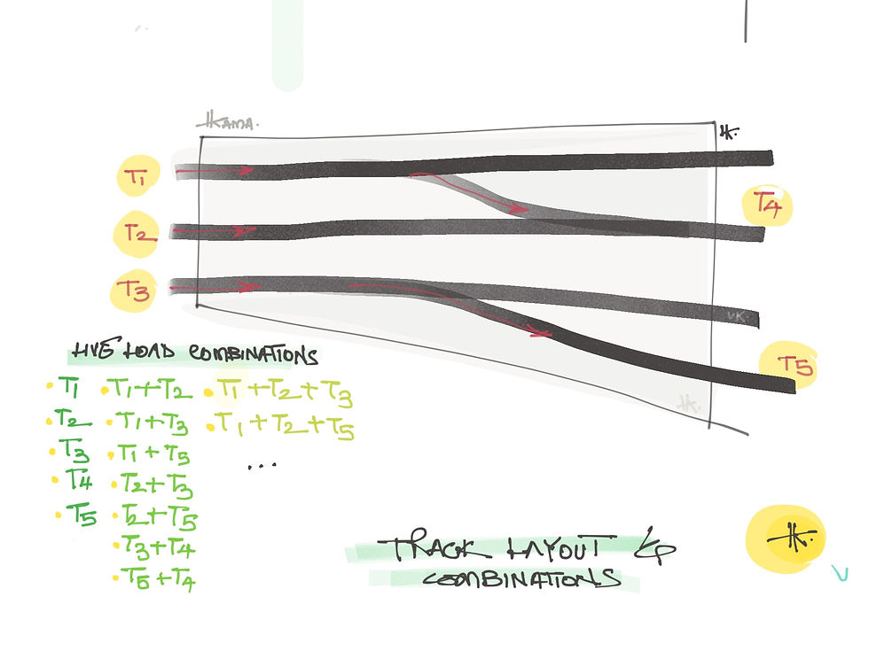
The track encountered upon this span are sketched above. Straight tracks T1, T2 & T3 are placed matching their centre line with the girder group for the track. For the curved tracks T4 & T5 they are laid on the slab with no coincidence of the girders in synchrony. It is only for the sake of nullifying the bending stress that the skew angle is resorted to. Another option might have been to keep the span rectangular, in that case additional girders might have been required and along with it the cost would reasonable escalate.
LIVE LOAD
The live load combinations are to be assessed as per the track layout. Since all the tracks cannot run all at once, the maximum number of metro bogies running on the span is limited to three. A bogie running on T4 cannot do so unless T1 and T2 are both empty. Similarly, if a bogie need to run on T5, T3 cannot be considered. So combinations are generated using all single tracks running individually, bogies running in groups of 2, and 3 bogies running at once. In view of this logic, we generate about 14 possibilities. All these load cases must be input in the grillage model as individual load cases with the increment of impact factor as per the relevant codes
An important factor for load consideration is the application of superimposed loads. In my analysis, I use plinth loads in the category of SIDL plinth loads. Now for straight tracks the plinths follow a straight line but for the curved tracks, the plinth is varying. In the sketch I have indicated the straight line and the curved track line.

The plinth dimensions, to which there is no global uniform, fuse into the plinths of the straight tracks. Often, the plinth is just made a singular wide block and no merger is explicit. While defining loads for plinths, the percentage of the plinth that protrudes must be made a part of the final calculus for finer results. This can be done by, again, dividing the transition length of the curve into segments and drawing offsets to the straight line and finding out the amount of protrusion.
CONSTRUCTION STAGES

To assess the actual stresses developing on the girders and bearing reactions, etc. we need to model constructions stages in the software. Now, what component you wish to activate I a matter of understanding how the construction progresses on site coupled with your assumptions. For my simplicity in analysis-I model for 3 construction stages, each of which has a uniqueness to it.
As you find indicted in the sketch, all girders are activated in the first construction stage along with the bracings joining the girders only and the diaphragms joining the girder only. Since girders are activated, all boundary conditions must be activated respectively in the same stage.
If you wish to wedge in more stages, be careful as to activate the corresponding boundary on both sides only and not all. If dead load is applied on the girders as a command, the loads will be automatically activated and the results will be reflected. Similarly the 2nd construction stage activates the bracings and diaphragms throughout. In the final stage, the concrete slab is to be activated which will complete the model. Duration of these stages must be set appropriately to the site status quo.
Subscribe to the BridgeHAWK® channel on #youtube
Follow us on Linkedin and stay updated!
HASHTAGS
#bridges #bridgeengineering #civil #civil3d #civilengineeringworld #civilengineering #civilengineer #civilengineers #civilengineeringstudents #civilconstruction #civilengineeringdesign #civilengineeringdiscoveries #civilworks #civilengineeringlife #creativity #creativityskills #creativityisnow #bridges #bridgeengineering #bridgeconstruction #bridgedesign #bridgeinspection #bridge #bridgebuilding #structural #structuraldesign #structuralengineer #structures #structuralengineering #structuralanalysis #structuralmodeling #structuralsteel #structuralhealthmonitoring #3d #3dmodeling #3dartist #3drendering #3dmodel #girder #boxgirders #construction #concrete #steel #posttensioning

Comments